


- Home
- About Us
- Sailing Courses
- Powerboat Courses
- SLC - International License
- Yacht Vacations
- Find an On-Water Instructor
- Practical Courses
- Fighting Childhood Cancer
- Free Courses Signup
- Student Benefits
- Gift a Sailing Course
- Sailing Opportunities
- Sailing Licenses and Certifications
- About the Sailing Certifications
- Sailing Blog & Helpful Articles
- NauticEd Podcast Series
- Yacht Charter Resources
- School Signup
- Instructor Signup
- Affiliate Signup
- Boat Sharing Software
- Sailing Industry Services
- Support & Contact
- Newsroom
- Privacy Policy
Boat Electrics 101
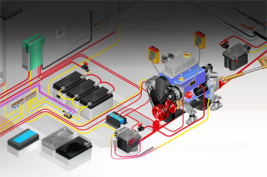

Take Control of Your Boat’s Electrical System
Boat owners know electrical problems cause more downtime than anything else. Boat Electrics 101 from BoatHowTo gives you the essentials to design, maintain, and troubleshoot your DC system correctly. Built by Nigel Calder, Dr. Jan Athenstädt, and Michael Herrmann, the course follows ABYC and ISO standards so you learn proven, reliable methods.
✓ For boat owners and cruisers upgrading or maintaining onboard systems
✓ Covers fundamentals, batteries, charging, distribution, and safe design
✓ Taught by leading marine technical experts
✓ Recognition on your NauticEd online resume
✓ Lifetime access with updates
Estimated Time: 12 hours (93 lessons, video + text)
Price: $199 Today (Normally $299 - You save 33%)
Bonus: All NauticEd sailing students receive the free Basic Sail Trim and Nav Rules courses, free eLogbook and Boating Resume, and special discounts from our industry partners. What's Included >
What Students Say
✨AI generated from student reviewsStudents report that Boat Electrics 101 turns confusing boat electrical systems into something clear, logical, and manageable. Even owners of older and complex boats say they now understand how all the components work together and feel confident planning upgrades like new batteries, alternators, solar, and DC-DC/B2B charging. Many describe feeling “empowered” to do their own refits, make smarter decisions when hiring contractors, and hold informed discussions about safety and system design. Learners highlight the course’s clear explanations, practical diagrams, and step-by-step approach as standouts, noting that it saves them time, money, and anxiety. Overall, they see it as comprehensive, excellent value for money, and more than a one-time course—an evolving learning platform they return to again and again.
Why Take the Boat Electrics 101 Course?
Register for the Boat Electrics 101 online course and learn how to understand, maintain, and upgrade your boat’s DC electrical system with confidence. This course gives you clear guidance on batteries, charging systems, wiring, and safe system design, so you can prevent failures and keep your boat running reliably.
If you own or plan to own a boat, this course builds a solid foundation in marine electrics — helping you move beyond guesswork and dockside advice. From understanding how power flows through your system to recognizing and fixing common faults, you’ll gain the skills to manage your boat’s electrics with the same confidence you bring to the helm.
Includes practical demonstrations and diagrams that make complex electrical concepts easy to apply on your own vessel.
THIS BOAT ELECTRICS COURSE IS PERFECT FOR YOU IF…
-
You want fewer electrical breakdowns and more reliable time on the water
- You’re preparing your boat for cruising or charter ownership and need dependable systems
- You’re planning upgrades and want to ensure they meet proper marine standards
- You value professional-level knowledge, not trial-and-error learning
- Your enrollment includes lifetime course access and free updates as technology and best practices evolve.
Your enrollment through NauticEd includes lifetime course access, a complete satisfaction guarantee and free addition to your NauticEd resume.
Written and Endorsed by Nigel Calder
WHAT YOU’LL LEARN IN THIS BOAT ELECTRICS COURSE
Understanding boat electrics is pure prudence. Thwarting Murphy in his attempts to turn the lights out at the perfectly wrong time is a requirement for any boat owner because electrical failure is not an "if" but a "when".View the Course Topics
Electrical Foundations
- Core principles of DC electricity (voltage, current, resistance)
- Safe handling practices and avoiding common onboard hazards
- Reading and understanding simple wiring diagrams
Power Sources & Storage
- Battery types, selection, installation, and maintenance
- Charging methods: alternators, solar, shore power, and wind
- Proper cabling, fusing, and protection for safe energy distribution
System Design & Troubleshooting
- Planning and installing reliable DC circuits
- Identifying and fixing common electrical faults
- Using diagrams, meters, and best practices to prevent failures
Upgrades & Emerging Technology
- Integrating solar and renewable charging solutions
- LED lighting and modern onboard electronics
- Designing for efficiency and long-term reliability
MORE ABOUT THE BOAT ELECTRICS 101 ONLINE COURSE
- Learn how to design, maintain, and troubleshoot your boat’s DC electrical system — from fundamentals to full system planning.
- Duration: Approximately 12 hours of lessons (93 topics), self-paced—learn at your own speed.
- Unlimited Access: Lifetime access lets you review anytime. Free updates as standards and practices evolve.
- Recognition: Upon successful completion, your NauticEd resume shows your electrical systems knowledge—valuable for owners, surveyors, and charter operators.
- Convenient Formats: Take the course on your desktop or laptop—or on tablet and mobile using the NauticEd App.
- Highly Recommended: Built by the world’s leading marine electrics experts and trusted across the industry.
Price Today: $199 (Normally $299 - You save 33%)
ABOUT THE AUTHORS & BOATHOWTO
Boat Electrics 101 was created by BoatHowTo and is led by boating legend Nigel Calder, the most trusted resource for technical boat systems. Nigel's team behind the course brings unmatched authority in marine electrics:

Nigel Calder – Widely regarded as the world’s leading marine technical author, best known for Boatowner’s Mechanical and Electrical Manual and his decades of work shaping ABYC and ISO standards.

Dr. Jan C. Athenstädt – Marine engineer and educator who has taught electrical systems at universities and boatbuilding schools, specializing in clear, practical instruction for boat owners.

Michael Herrmann – Professional boatbuilder and systems expert with decades of hands-on experience installing and troubleshooting yacht systems across Europe.
Together, they founded BoatHowTo to provide reliable, standard-based instruction for boat owners who demand more than guesswork or dockside advice. Their mission is simple: make advanced technical knowledge accessible, practical, and safe.
BoatHowTo’s courses are trusted by boat owners, surveyors, schools, and professional installers worldwide. By partnering with NauticEd, this expertise is now available directly in our course directory.
View Boat Electrics 101 Course excerpt
List Price: $199.00
Excerpt from the course
Expand Excerpt from the courseBasic Electric Troubleshooting
Problems in electrical systems can almost always be traced to one of four causes:
- resistance in connections
- breaks in conductors
- short circuits in conductors
- the failure of components or devices
Troubleshooting typically consists of using voltage, resistance and current measurements to detect unwanted resistance, or a break in a conductor, or a short-circuit. If none of these conditions exist the circuit is most likely OK, in which case the device has probably failed.
|
For example: If there is no output from a solar panel, the panel itself may be defective (device failure); the connection between the panel and its controller may be corroded, broken, or short-circuited; the controller (another device) may be defective; or the fault lies in the connection between the controller and the boat’s electrical system. |
The task of troubleshooting is to use a logical process to find the resistance, interruption, or short circuit, or to determine which device has failed.
In this lesson, we will describe techniques that will, in most cases, quite quickly enable a problem, together with its location, to be identified, even if the problem is hidden behind paneling or in a conduit.
Basic Tools
A key tool is the eye. A visual inspection often reveals that a connection is corroded, a conductor broken, or a module has failed due to mechanical damage. Sometimes the nose comes into play. For example, burned motor windings have a distinctive smell, as do overcharged wet-cell (flooded) batteries that are venting sulfuric acid. And then there is touch: warmth or heat is a sure sign of excessive resistance. However, it is important to be careful here – sometimes resistive connections can become hot enough to cause instant burns, and of cours,e live AC components can kill you! Ideally, you will have an infrared thermometer or thermal camera to check for heat.
All too often, conductors and connection points are not accessible and thus evade visual inspection. And you can’t tell from looking at the outside of a device whether something internal has failed. If you jump to premature conclusions about why something has failed, you are just as likely to make the problem worse as you are to fix it. The fastest and safest approach is to narrow down and isolate the fault with methodical testing and measurement. This is what we will do in this module using a multimeter as our principal tool.
Multimeters
Given the prevalence of electrical system problems on boats, a multimeter is, in our opinion, the single most useful tool to have on board, so long as you know how to use it. We hope at the end of this lesson, you will have the necessary knowledge to track down most problems. But first, we must decide what features we want in our multimeter and how much we are willing to pay for it.
Traditional multimeters are analog devices (with a swinging arm). If you have one of these, you should consider replacing it with a digital meter.
No Cheap Meters!
You should avoid cheap meters for two reasons. First, you want a robust housing; experience has shown that the meter is likely to have to survive tough encounters with floorboards or bilges. Second, you absolutely want built-in safety features that will prevent meter damage and potential personal injury if you accidentally use the meter incorrectly. For example, resistance (ohms) measurements require a circuit or device to be isolated from its power source (see below). If voltage or current is present, a cheap meter may be destroyed. At best, a fuse will blow.
Higher-quality meters will protect themselves. Somewhere on the meter, you want to see it stamped, at a minimum, 'CAT II', and preferably 'CAT III 600 V'. A higher quality meter will likely also be stamped 'CAT IV 300 V'. There should also be a UL, CSA, and/or CE mark to indicate it has been tested to a recognized standard.
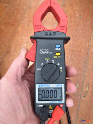
A meter with separate AC & DC switch positions, which we recommend
|
What to spend? How much should you expect to pay for a multimeter? Without a DC current clamp, you can get some decent meters for under $100. If the DC current clamp is a condition of purchase, which we recommend, you can find some meters priced as low as $60 but ideally you should be willing to spend anywhere up to $300. The more you spend, the more safety features you are likely to get, with more rugged construction, and a higher level of accuracy. In the U.S., the gold standard for meters is set by the Fluke company. At a little under $300, the Fluke 325 has all the features mentioned, except for a diode tester. The Blue Sea Systems 8110 meter has similar features for ~$150. Nigel recently found a meter from Intendvision, with a CAT III certification, which has all the functions of these meters and more for $36. He bought three just to see if this was for real and it is! Maybe it's a pricing mistake that will not last. |
>>>>
Nigel and Jan's course contains 93 lessons on how to troubleshoot, fix, and upgrade your boat's electrics. Get the course now.
Trusted by the world's leading sailing companies
From our students
4.9 out of 5 average across 74,525 student course ratings.
-
"I liked that there wasn’t pressure to rush. I could actually understand what I knew and what I still needed to work on."
Jamie, first-time boater
-
"By the time we chartered, I felt prepared instead of just approved. That made all the difference."
Alex, preparing for bareboat charter
-
"NauticEd helped me see boating as a skill I could build, not something I had to pass or fail."
Morgan, new boat owner